Repairing a 1980s solid state bingo pinball machine
For about 20 years my parents have had a broken WIMI Miss Bonus sitting in their basement. Every time you start it up, its "Magic Lines" just keep spinning, and nothing happens. This summer, I took it upon myself to finally diagnose and fix the machine. It required a lot more effort than I initially anticipated, but it was very interesting to see how it all worked, and I learned a lot from it.

The WIMI Miss Bonus
If you're just interested in the schematics, manuals and ROMs I found, feel free to download those here:
Spinning motors
The machine with its 5 magic lines spinning (backglass removed)
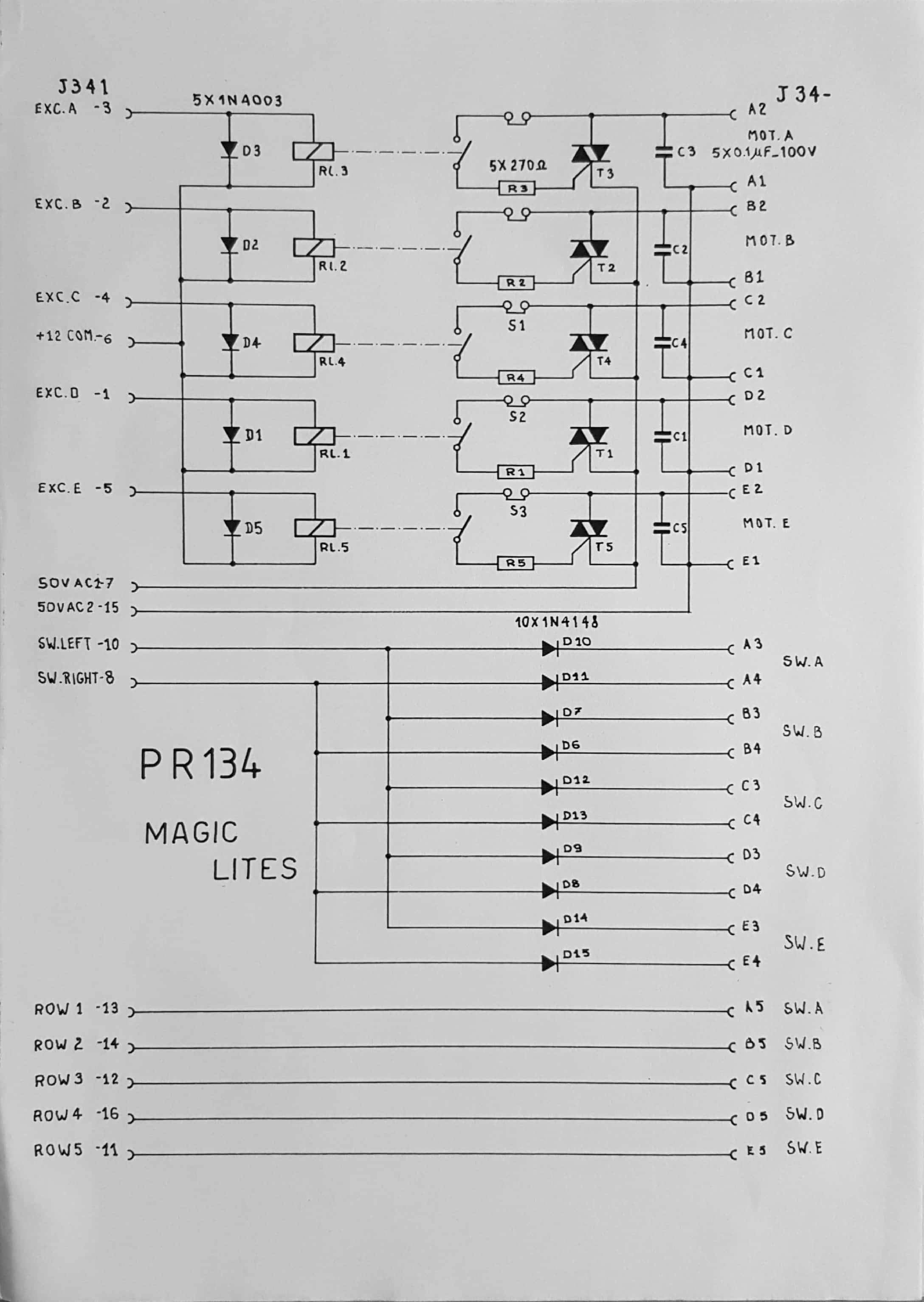
I started with figuring out why the motors were spinning and how I could get them to stop. The magic motors are controlled by circuit board PR134. It consists of a relay that controls a triac per motor. The relay offers ground isolation between the 50V motor circuit and the 5V CPU logic circuit, and the triac turns the motor on and off without arcing. One of the relay pins is connected to 12V, and the CPU can pull the other to 0V to turn a particular motor on.
So there are three possibilities: (a) the CPU is pulling all motors low, (b) some relays are stuck closed, (c) some triacs have failed short.
I started by cleaning the relays and fixing some bent motor arms. Now two more motors (that originally weren't doing anything) also started spinning, so all 5 were now stuck spinning. A part of me had hoped that the two non-moving ones were actually good, and that the CPU was able to "home" them but not the others. Anyways.. progress, I guess? I also measured the triacs, they looked fine as well.
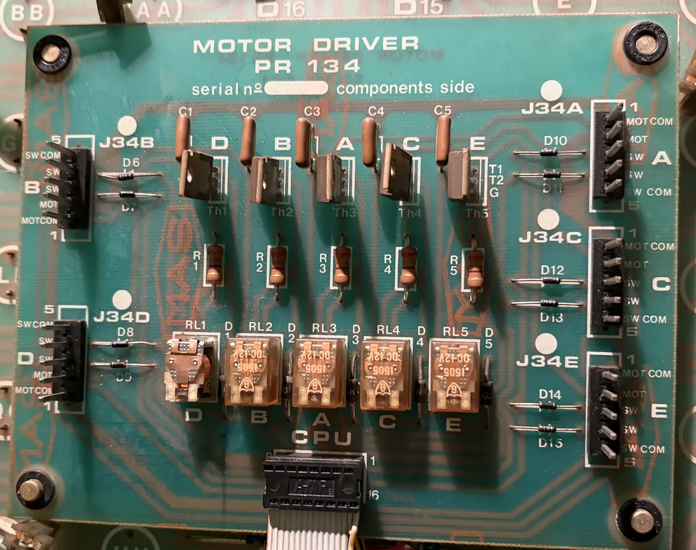
The PR134 motor driver board: one relay (bottom) and triac (top) per motor
The CPU
Since the CPU board is what controls this motor board, this is where I looked next. All logic on this machine is controlled by an intel 8085 processor. It has two 5101 chips used as persistent RAM for stats, and three 8155 chips for I/O, (stack) RAM and timers. It thus uses memory mapped IO. The program itself is stored on 5 ROM chips, storing 2K each. The board uses 74LS138 decoders to decode the address and enable the right ROM or RAM chip. It also has a lot of 7406 inverters, used as a current amplifier for all control lines (for example going to the magic motors and to all the lights).
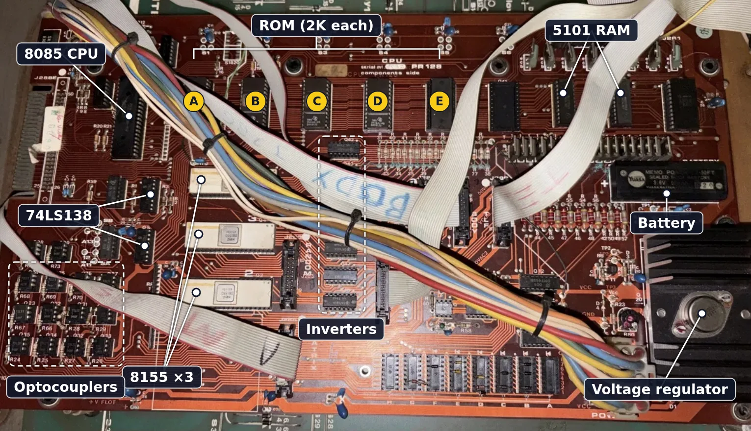
The PR128 CPU board
Looking at this circuit could immediately explain why the motors keep spinning. If the CPU never configures the 8155s, its ports become inputs, they float, which the inverters could see as HIGH, turning the motors on. To know for sure, we need to take some measurements. I took my old analog oscilloscope and started with measuring the CPU.
Measuring the CPU
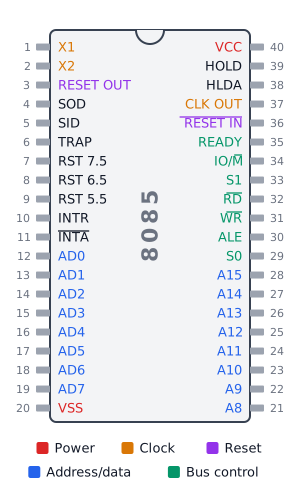
The Intel 8085 pinout
Measuring the X1,X2 and CLK OUT pins immediately told me the crystal was oscillating and a proper 3MHz clock signal was being constructed from it. Good.
Next, I looked at ALE. The 8085 reuses the bottom 8 address pins as data pins (AD0-AD7). At the start of every machine cycle, an external latch needs to grab on to the address pins before they switch over to carrying data. The latch is instructed to do this using the ALE pin, meaning if we see a train of pulses here, the CPU is probably executing instructions. And.. it was! Great news, or not so great, because what could be wrong now?
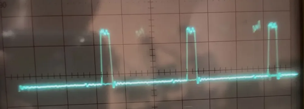
Pulses on the ALE pin: the CPU is running
I also checked the reset pins, which were high, so the CPU wasn't being reset. Then there's the IO/M pin. It tells the rest of the board whether the CPU is doing IO or memory. As we've already established, all I/O happens through MMIO using the 8155 chips, so this pin should be low. However, it was floating. That's definitely weird, the CPU should be driving it, but it can't be the cause of our issue as this pin is entirely unused in the schematic. Looking further, I also checked the WR pin. We expect to see a mostly high signal with occasional dips, to indicate the CPU is writing. But again, this pin was floating. This indicated a real problem, as the CPU needs to be able to write to do anything useful. The logical next thing then would be to try a new CPU. They can be found online for €5-€10, with quick delivery times on Belgian, Dutch and German stores.
The clock is ticking
I put in the new CPU and.. nothing. Not even a CLK OUT. What?? Did I get a broken one? No, it turns out the crystal oscillation somehow wasn't strong enough for this new CPU, and it wasn't able to create a clock signal from it. So I ordered a new 6.144MHz crystal.
To be able to continue testing, I used the timer in my Arduino Uno to create a 4MHz (16MHz/4 on the Arduino, the CPU turns this into 2MHz) clock signal, and injected that directly into the CPU by bending the pins up and connecting it to my Arduino. I started it and it worked! As expected, the floating pins from before now show their expected values. Real progress, as the display on the front of the machine also started showing error codes. I finally wasn't blind any more.
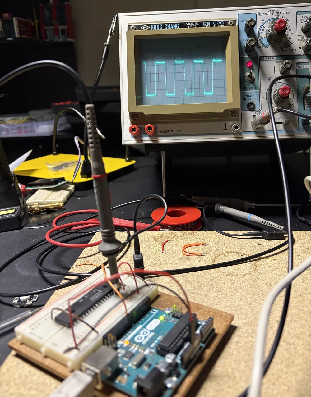
The CPU out of the board, clocked by the Arduino
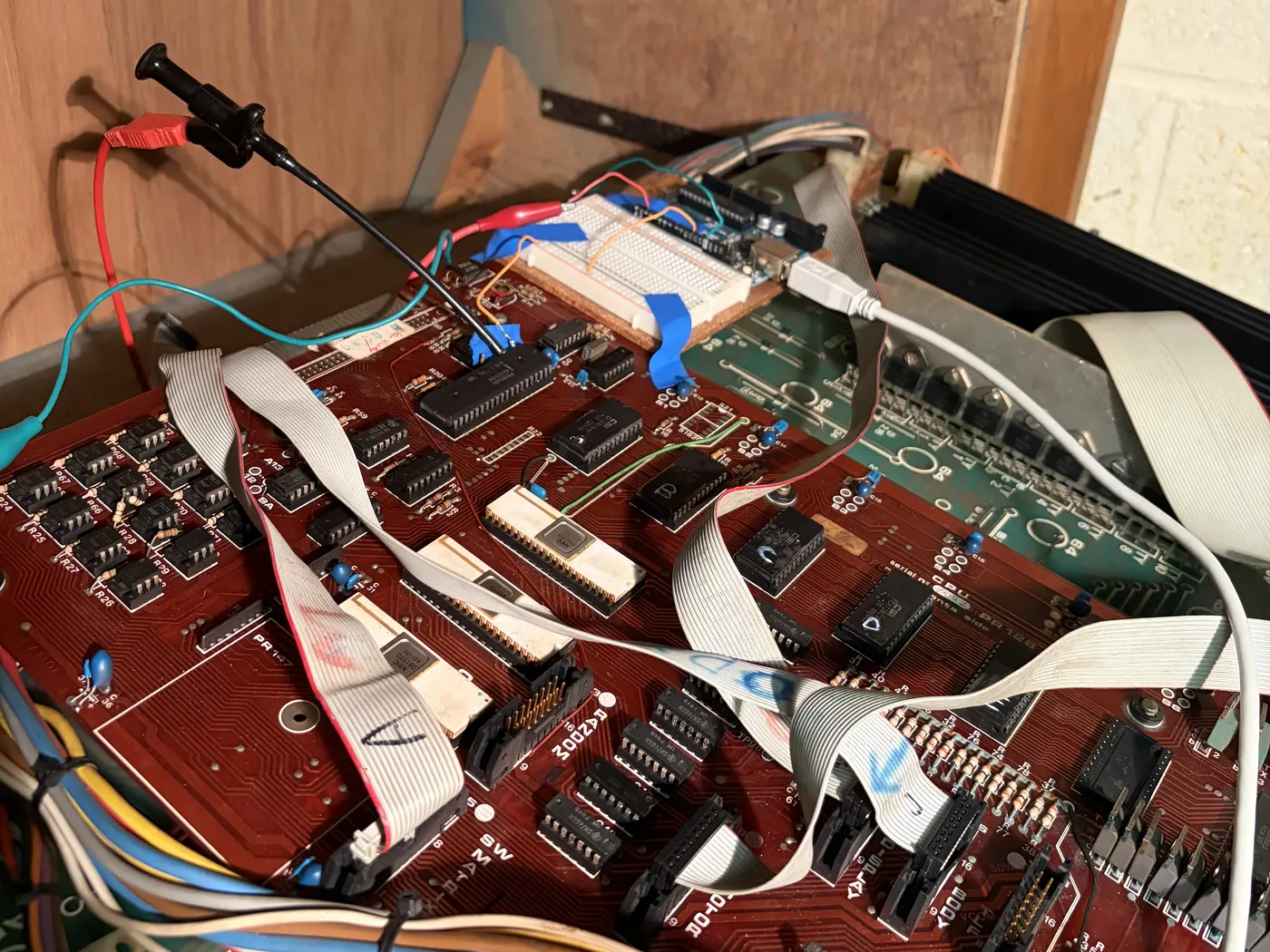
Back in the machine, with the clock pins wired to the Arduino
Roms A B C ? E, Miss Americana?
Unfortunately, the codes on the screen weren't helpful yet as I hadn't yet found a manual for this machine. Either way, I bought a T48 chip reader and started by reading out the ROMs. All of them read out fine, except for the fourth one, which gave different values across the chip every time it was read out.
I tried everything: freezing the chip, heating it. This would help stabilize some bits, but not enough to be able to reconstruct it. I did over 15000 reads of the chip, hoping to find some kind of statistical evidence for the real values. I even had (the then recently released) Fable 5 look at it, attempting to reconstruct the binary from the statistics and possible legal assembly instructions. It came up with something it was 90% confident in, but ended up being completely wrong.
Anyways, the chip was toast and I ordered 5 new ones, EEPROMs now, so that I can rewrite them to my desire. Before these arrived, I did a last effort attempt: computing the SHA-1 of one of the good chips and looking it up online. And I found a zip with 5 ROMs, all 4 good ones matching, for a WIMI Miss Bonus Sirmo Miss Americana? What? That's not my machine? Apparently these use identical ROMs, and after doing some more digging I found the circuit boards are identical as well. On top of that, this machine did have a manual for it online, with common faults, an entire explanation of these first gen solid state machines and how they worked, and a table with the meaning of the error codes. I had struck gold and was feeling confident the machine could be repaired.
These 5 ROMs also told me Fable 5's reconstruction wasn't identical, with about 10% of bytes wrong in some way or another. I never ended up testing it.
Random generator?
When I first opened the machine, I also found a taped up PCB labeled PR147 Random Generator. I thought this would be quite essential, as a gambling machine needs randomness. I plugged it in at the start, before all the other debugging (reversed, as its connector was put on the wrong way), it got quite hot, but didn't change anything about the behaviour of the machine. Analyzing the ROMs, I found out this is actually not a random generator at all, but rather appears to serve as an anti-copy device. Without it solving a small puzzle every once in a while, the machine makes itself crash. I nopped it out, and never worried about it again.
Getting it to talk
When I first booted the machine with the new ROMs, I was greeted with an error telling me it was upset that its persistent RAM had been reset. According to the manual this happens when the magic bytes it writes to its persistent RAM are gone. Rebooting should fix it, as the code for the error also writes them again.
But of course, a 40+ year old battery doesn't hold charge anymore, and I had already removed it at the start as it was leaking its corroding juices all over my board. To get past this error, I nopped out this code from the binary.
The machine booted, but nothing really happened apart from some lights coming on. I needed a better way to debug the system. I gave Fable 5 a second attempt at proving its worthiness, by having it write me a custom debug ROM that would allow my laptop to connect, via my Arduino, to the bingo machine over its serial SOD/SID pins. And prove its worthiness it did, it wrote a full CLI parser in pure assembly and allowed me to poke at memory addresses, reading and writing to see what happens. It also set up the I/O chips in the same way the original ROM does, so I could test its outputs (though it needed multiple attempts at this, I forgive it).
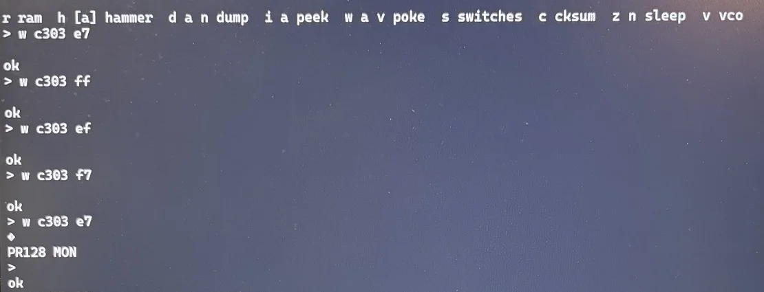
The debug ROM's command line, seen from my laptop: writing values to address C303, until the last write resets the board
Overclocking a bingo machine
A short aside: my new crystal had arrived by now. I soldered it in but it started oscillating at an overtone, making the CPU run at 9MHz, three times as fast as it was designed for! For a moment, it was the fastest bingo of its kind in the world, but obviously the CPU quickly crashes like this. I fixed it by soldering in two 22pF capacitors to ground.
More faults
Decode my bits, please
I first started by testing the memory, writing to all addresses in a loop and reading back. Immediately an issue became apparent: one of the 5101 RAM chips was broken. They are set up such that each chip stores one nibble of each byte, one chip doing the bottom half and the other the upper. One half was always 0, for every address, and swapping the chip moved the half. So that needed replacing.
Next, I started writing to the I/O addresses set up for the 8155 chips. Its ports are hooked up to the 7406 inverters, which then go to lights, motors etc. I should be able to control every motor and light row, and I started with the magic motors. Measuring with my scope, I could see nothing was happening at the output port. Measuring a little further I found the right chip wasn't even being enabled. The board uses 74LS138s to decode the address and select the correct 8155 chip (there are three), but one of its outputs was clearly broken. I replaced it and voila, the signal made it to the inverters (and the assumed floating causing the spinning from the start was fixed). I could finally enable and disable some motors at my command, by writing zeroes and ones to their designated bits. Not all motors worked, because a lot of outputs on the inverters were also broken. So I had to replace those as well.
I'm pressing the damn button
Now that the motor outputs were fixed, I started testing the inputs. Going over each and every single switch, and expecting its corresponding bit to flip when I press it. The switches work through a scan circuit, where the switches are setup in a matrix with diodes, and rows and columns are pulsed to find all combinations that are on. To isolate the logic ground and button ground, optocouplers are used.
It turned out one of these was broken, but luckily I had a replacement that came with my Arduino Uno kit. Many other individual switches weren't working because of bad contacts. I had to resolder every single switch on the playfield, rebuild some switches in the motor mechanism, bend the motor lifter back into place (it was stuck) and relube the motor lifter switch (it detects that a ball is at the bottom of the lift). Also the collect reward switch was wrongly wired, someone had worked on this before. Great, all buttons work now, what's next?
The lights need power
This really was a magic moment. I put the game ROMs back in (with their patches), and I finally had a working game. Using the remote control box TLF, I could add credits and play a game, but no lights showed up.
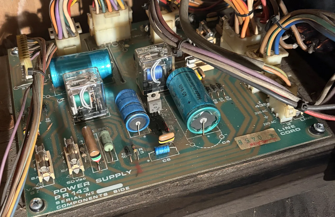
The PR143 power supply
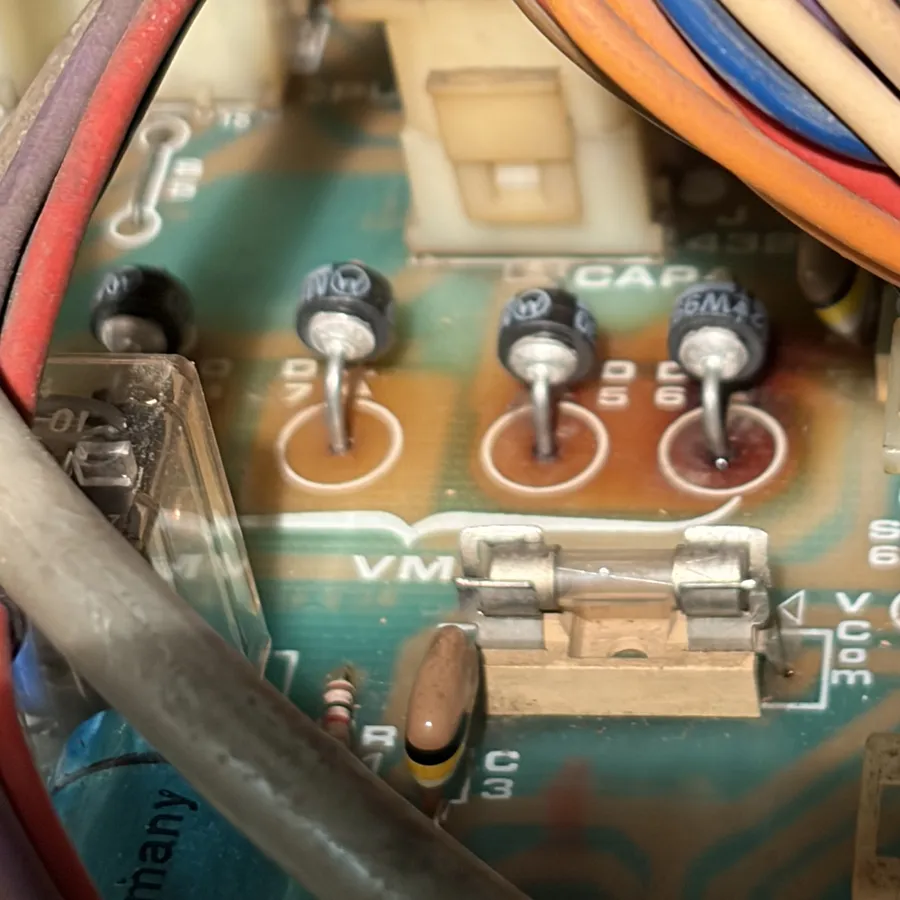
The four diodes of the full bridge rectifier
The problem was obvious: the power supply wasn't even outputting a voltage on the lights rail. Suspiciously, the fuse for this rail was also missing (again, I'm sure someone worked on this before). Adding it back didn't fix the issue, but it also didn't blow. I took out the power supply and measured it. It's a linear power supply, so its functioning is very simple: transformer -> rectifier -> filter caps (-> linear regulator). In my case one of the diodes in the Full Bridge Rectifier had broken shorted. Its resistance was barely enough to not blow the fuse. I went to my local electronics store, My-TEC, and to my surprise they still had the original diode model from the 80s lying around and gave them to me for free. Thanks! It fixed the issue, there was now a voltage on the lights rail.
Turning on the machine also showed some lights, but then I suddenly heard a loud buzzing noise. Some of the sound-making coils were being forced closed. After some digging I found this was also controlled by the lights circuit, but the root cause was unexpected. Because I had previously nopped out the ram-lost-battery code, this ram wasn't being initialized properly. It was therefore reading a garbage gamestate, causing some coils to be stuck on. Easy fix, remove my nops and put in a new NiMH (no more NiCd) battery.
How does one control 100 lights
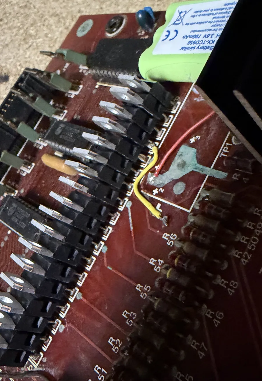
The replaced darlingtons, a repaired trace and the new battery
This was the first time I could play a proper game, but the lights were still acting up, with many of them still not working. The lights circuit works very similarly to the scan circuit. Its a matrix with rows, columns and diodes, and the CPU pulses over all combinations it wants to turn on. The CPU pulls one side high and the other low, so current can flow through the bulbs. Now obviously our little I/O ports or even inverters cannot supply the multiple amps of current these lights need. That's why there are several amplification stages, including darlingtons on the CPU board, and big power transistors on the lamp board. I replaced all darlingtons on the CPU board, as many measured weirdly and they were all green from the battery corrosion. I also had to repair some damaged traces around the area (one column was flickering) and 3 of the power transistors needed replacing (measured short between C&E).
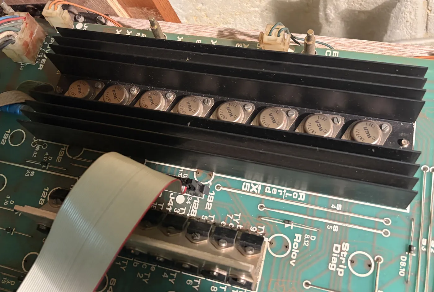
The power transistors on the lamp board
Everything now works, perfectly. The machine starts, I can add credits, play a game, move the magic lines, and obviously win all credits I put in back (sometimes).
Peace of mind: new filter caps
One more thing I wanted to do, so I can sleep soundly, is replacing the old huge filter capacitors. The old ones were of the type that stand up without a PCB, which is a lot more expensive than regular ones you put in a PCB. I therefore 3D printed a small mount for my new capacitors to sit in, and hooked them up.
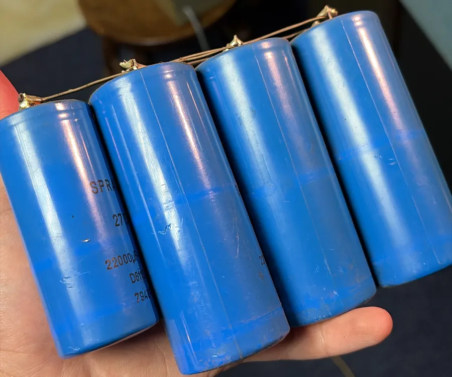
The old filter capacitors
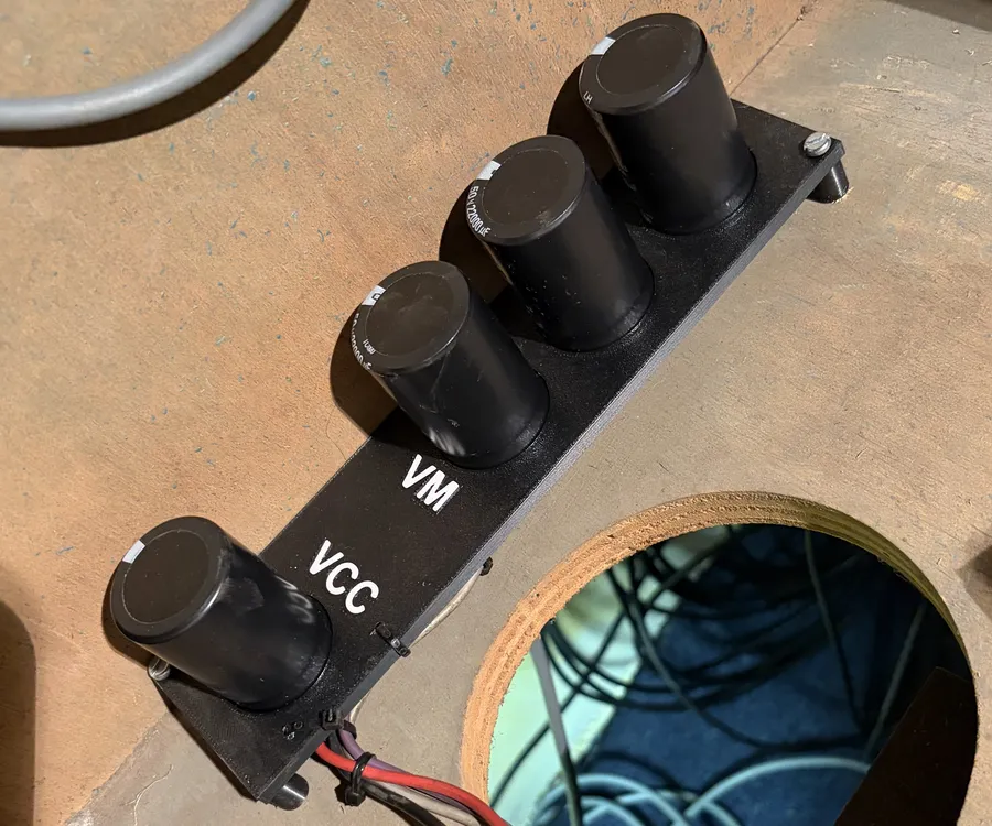
The new capacitors in my 3D printed mount
Conclusion
After 20+ years of spinning magic lines, the Miss Bonus works again. It wasn't one big fault but a long list of small ones, stacked on top of each other so that each one hid the next (in a very educational way).
In total I replaced: the 8085 CPU, its crystal (plus two caps), all E(E)PROMs (including the broken ROM D), the 5101 RAM chips and their battery, some 74LS138s, several 7406 inverters and an optocoupler, the full bridge rectifier, all darlingtons on the CPU board, a few traces and 3 power transistors on the lamp board, the filter capacitors, and countless switch contacts on the playfield. And I enjoyed every moment of it.
Even though I replaced a lot of parts, it's only a fraction of what's on the boards, so measure before you replace. It allows you to see what's wrong and learn how the machine works. Almost every fault here was found by poking around with a scope and knowing what signal to expect. Another tip would be to look beyond your own machine: finding the Miss Americana ROMs and manual was very useful in this repair, and I only stumbled on them by accident. And building your own tools, like a debug ROM, can be extremely useful as well.
I hope this was an interesting read, and if you by any chance have one of these machines sitting in a basement somewhere, maybe this helps you get it going again. Feel free to leave a comment below and tell me your thoughts.
Sources
- ROMs: downloaded from Planet Emulation
- Manual: the Miss Americana technical service manual from the Arcade Museum
- Schematics: Understanding Bingo Machines on Flippers.be, which has a collection of manuals and many (unlabeled) WIMI schematics